WAGO CC100
In order to install logiccloud Control on your WAGO CC100 device, you must first deactivate the CODESYS Runtime and install Docker on your CC100. You can find the instructions here: Install Docker on WAGO CC100. You can find video instructions from WAGO on YouTube.
Install Docker on your WAGO CC100
Section titled “Install Docker on your WAGO CC100”- Download the latest Docker Runtime for the CC100: Docker Runtime for CC100 Under Releases on the right side you will find the latest version
docker_20.10.14_armhf.ipk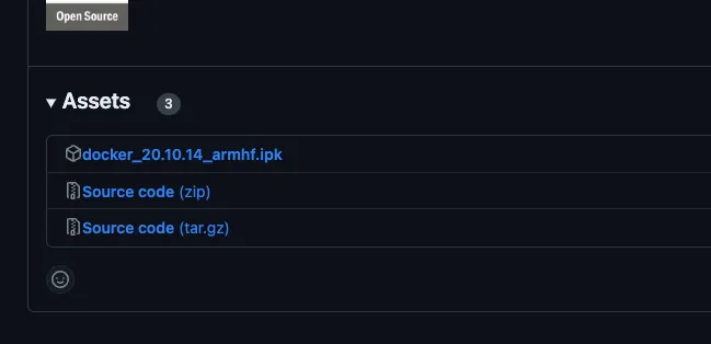
- Next, log in on your device by calling up the
Device IPin the browser, for examplehttps://192.168.178.120. The default access data areadminandwago. - Click on Configuration and then Clock and check the set system time. This must be correct for the installation to work.
- Click on Networking and add a DNS server under TCP/IP Configuration, for example the one from Google with the IP
8.8.8.8, so that the images can be loaded from the Docker Hub. - Click on Networking and activate the IP Forwarding through multiple interfaces option under Routing.
- Click on Software Uploads and upload the previously downloaded Docker Runtime and install it via Install.
- As soon as the installation was successful, you can connect to the WAGO CC100 via an SSH client, for example Putty, and check the Docker version. The access data are ‘root’ and ‘wago’ by default.
docker -v# Docker version 20.10.14-wago, build f0df241Install logiccloud Control
Section titled “Install logiccloud Control”To install logiccloud Runtime on your CC100, please follow the instructions here: install logiccloud Control.
logiccloud Control Runtime
Section titled “logiccloud Control Runtime”To access the inputs and outputs of your CC100 controller, you only need to create an access variable for each input and output. You can then assign this to any process variable within the project.
// ACCESS VARIABLES WITH TYPES// Analog Inputs, represented as INT 0-10000, not writableAI1, AI2: INT;
// Digital Inputs, not writableDI1, DI2, DI3, DI4, DI5, DI6, DI7, DI8 : BOOL;
// Temperature Inputs, represented as INT 6020-29535, not writablePT1, PT2 : REAL;
// Analog Outputs, represented as INT 0-10000, writableAO1, AO2 : INT;
// Digital Outputs, writableDO1, DO2, DO3, DO4 : BOOL;